
Screen Designs for v0.1.0 (beta test version)
The initialisation, calibration and operating screens will retain their current designs.
The programming screens will change as described below.
See also the Screen Mockups.txt attachment, which should be considered The Source of Truth for the actual options/designs.
Note that all the programming screens will display the selected turntable in the top right-hand corner, as per the current design. This leaves a 21x13 character block available for the programming functions.
Menu Structure
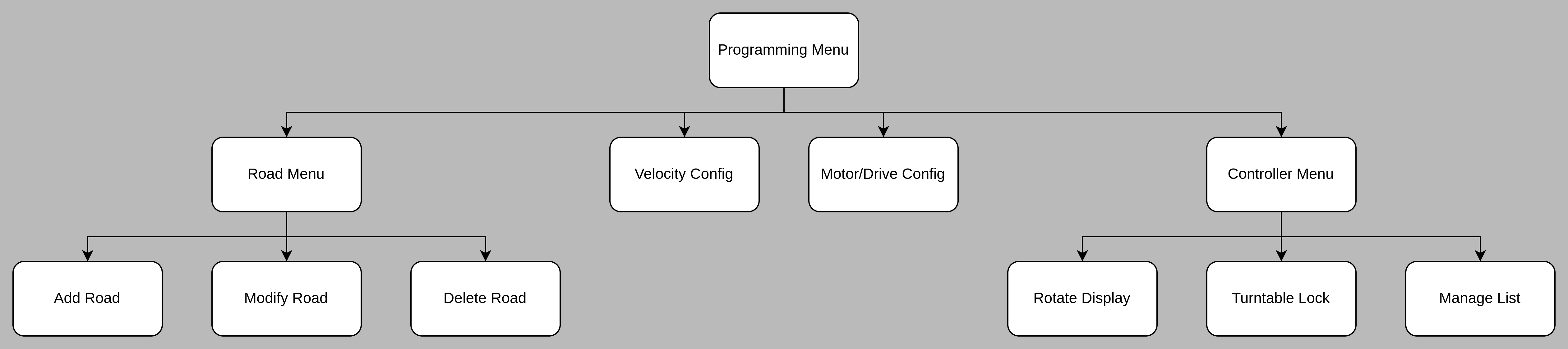
Initial Programming Menu
Currently, this screen allows you to move the turntable, add/modify/delete roads, or access any of the secondary programming functions using the four letter keys. The PROG button toggles between programming & operating modes.
This screen will change to be a pure menu screen, along these lines:
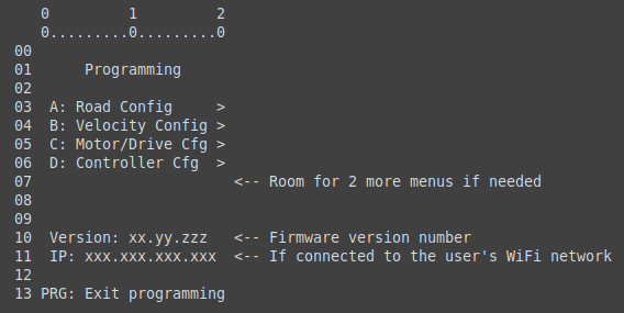
Pressing any of A-D will take the user to the next menu.
A: Road Config
This option brings the user to another menu, this time with three options:
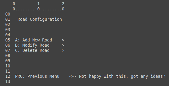
If no roads are configured, then options B and C will be dimmed, and pressing B or C will have no effect.
A->A: Add New Road
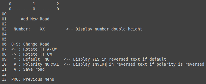
This screen allows the user to program a new road.
By default, the Number field will be pre-filled with the first available road number greater than zero; but the user can over-ride this by using the numeric keypad. After the first digit is pressed, if another digit is pressed within 1/2 second, a 2-digit number will be displayed. Thus, up to 100 (from 00 to 99) roads can be programmed.
The initial version will likely be limited to 9 roads for the time being.
Pressing <-- or --> will cause the turntable to rotate; whilst the buttons are pressed (and for approximately 1/2 second after release), the screen will change to show the turntable animation, as with the current system.
Pressing * will toggle this road to be the default road (i.e. the road the turntable goes to when first initialised)
Pressing # will toggle the track polarity. When the turntable is approximately half-way between its start position and its target position, the bridge polarity will be reversed if needed. If the tail of the turntable is sent to a road, it's polarity will be reversed if this setting is NORMAL. This function can be disabled if, for any reason, it is undesirable.
Press A to save the road. When the road is saved, the controller will set the road number to the next available road number, so the user can easily add all required roads in one setup.
If the user types in a road number which is already configured, the screen switches to the Modify Road screen for the selected road.
A->B: Modify Road
The screen design for Modify Road is identical to that of Add Road, with the exception of the title.
When Modify Road is selected, the system will find the nearest configured road to the current turntable position. If that position does not correspond to a configured position, the turntable will move (at rapid speed) to the selected position (the screen will display the turntable animation at this time).
This is to ensure that, if the user only wishes to modify the default and/or polarity options, that they don't accidentally reposition a road.
After the turntable move (if required) is complete, the menu is displayed and functions exactly as above, except when saving the road, the existing config is overwritten. After the road is saved, the screen does NOT change, until either the user presses PRG (to return to the previous menu), or types in a new road number - at which point the system switches to add or modify, depending on whether the road is already programmed, or not.
A->C: Delete Road
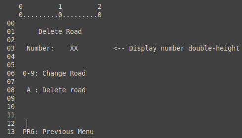
On entering this screen, the turntable will choose the closest road to its current position, and will display that number.
It will not, however, physically move to that position.
The user can over-type the number in the usual way.
When the user presses "A" to delete the road, the system will prompt them to press "A" again to confirm; any other key will return to the above display. If they confirm, the road configuration is deleted, and the system returns to the Road Config menu.
If the deleted road is the default road, the nearest road to the deleted road is automatically promoted to the default road. If the deleted road is the ONLY road, then the system simply returns to the Road Config menu, with options B and C dimmed as described.
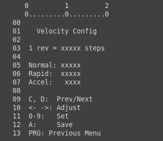
B: Velocity Configuration
Similar to the existing screen, slightly altered to keep "A" as the "Save" function.
Unlike the original screen, this one:
- Adds a bit of info (the number of steps for 1 revolution)
- Will allow you to type a number using the keypad
- Will show changed numbers in a different colour
- Will visually feed-back saved settings (colours revert to normal)
C: Motor/Drive Configuration
This screen replaces two existing screens - the calibrate screen and the "other settings" screen.
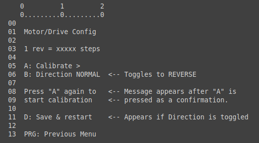
If calibration is carried out, the existing routine is used *except* that the resulting number of steps will be sent to the controller BEFORE being saved (the "Save & restart" message will appear if the number of steps is different to the current setting).
If the user toggles the direction to the opposite of its current setting, the "Save & Restart" message will also appear (if it hasn't already).
If the user presses "D" and the message is visible, the controller will tell the receiver to store the new calibration value (if it's different, and makes sense - i.e. is 6400 or some multiple thereof), and the direction flag, and will trigger the turntable to initialise, as it does now with the "other settings" menu.
D: Controller Configuration
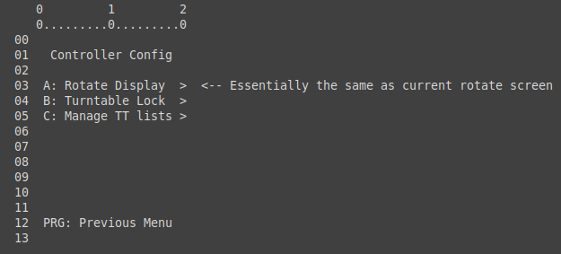
This screen replaces the "other settings" screen, and is another submenu from which other screens can be accessed.
D->A: Rotate Display
The "Rotate Display" option mimics the current "rotate display" screen, possibly slightly re-jigged to be consistent with the new screen options (e.g. PRG to return to the previous menu).
D->B: Turntable Lock
This is a new screen which allow the locking function to be controlled. By default, the locking function is DISABLED:
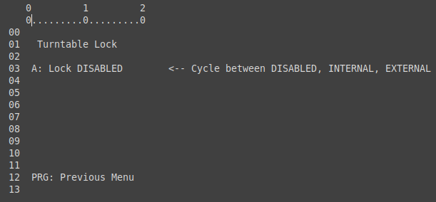
When Lock is DISABLED:
- The locking function is not used, and the output will normally be low.
If the user presses "A" to set the lock to INTERNAL (i.e. the locking pin is an OUTPUT), the screen changes as follows:
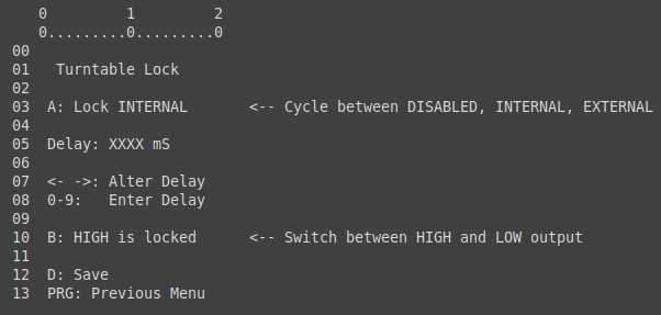
When Lock is INTERNAL:
- The lock/unlock signal is generated (i.e. it's an OUTPUT)
- Can be set to either HIGH or LOW = locked
- e.g. if HIGH, then the signal will normally be HIGH. When a Turntable move is requested, the signal will be set LOW, and after DELAY milliseconds, the turntable will begin to move.
- INTERNAL should be used if a physical locking mechanism is in use. The Delay setting allows time for the lock to retract before a move
- After the turntable has finished moving, the signal will be re-set to its locked state (HIGH or LOW), and the system will wait another DELAY milliseconds before allowing the next turntable move to be initiated.
- e.g. if HIGH, then the signal will normally be HIGH. When a Turntable move is requested, the signal will be set LOW, and after DELAY milliseconds, the turntable will begin to move.
When Lock is EXTERNAL:
- The lock/unlock signal is read (i.e. its an INPUT)
- The signal should be ~0v for LOW, and ~3.3v for HIGH. The input is 5v tolerant, but 3.3v is preferred. Use a level shifter if necessary.
- Can be set to either HIGH or LOW = locked.
- EXTERNAL should be used if an external mechanism (or "virtual" mechanism) is used to lock/unlock the turntable. e.g. a lever in a frame must be pulled ON to unlock the turntable; this lever should set the lock signal appropriately.
- The turntable WILL NOT allow a move unless the Lock input reads the opposite of the locked signal
- e.g. if HIGH, then the external circuit MUST drive the pin LOW (to GND) BEFORE the turntable can move.
- The Lock pin must be in the UNLOCK position for at least DELAY milliseconds BEFORE a turntable move will be allowed.
- If there's no actual locking mechanism on the turntable, the DELAY should be set to a low figure to prevent user frustration.
If the locking function is not set to DISABLED, then a padlock icon will be shown on the turntable screen when the turntable is locked, and any attempt to move it will either be delayed (set to INTERNAL), or denied entirely (set to EXTERNAL).
There is currently no feedback mechanism for the INTERNAL setting. i.e. the controller will assume that the turntable has unlocked successfully after DELAY milliseconds. Users who have an actual external lock system may wish to implement a mechanical power break to the drive servo when the lock is deployed; such that if it does fail to release when commanded, the system doesn't attempt to drive the turntable against the lock.
D->C: Manage Turntable Lists
Design TBC; but essentially this screen will allow the user to:
- Move this turntable up or down the letter list (e.g. from A -> B -> C, or B -> A, etc.)
- Un-assign this turntable from the controller (this option will be removed from the INIT screen)
Un-block any previously detected controllers, allowing them to be detected and added again.- This doesn't really fit here.... it's not exactly related to "a turntable".
- Also it needs to be editable if NO turntables are detected (e.g. if the user hit the wrong button when their only T/T was first detected!)
No Comments